The Arduino MKR 1000/Nano RP 2040 Connect is an example of one type of common IoT board, the single-board microcontroller (SBM). SBMs are simple devices that do not come with an operating system.
They are good for performing simple IoT tasks like reading from sensors and activating simple
actuators.
These activities revolve around the Arduino MKR 1000 IoT/Nano RP 2040 Connect Bundle. These are exercises that introduce students to the various physical sensors/devices and programming the Arduino.
This material introduces students to basic non-IoT Arduino elements. These include how to connect
components to a breadboard, how to program an Arduino board, how to process data on the serial port,
and how to manage data streams.
It gives you a bunch of options. Make sure everything is checked.
During install, it will ask if you wish to install drivers. Always say yes.
Open the Arduino IDE.
Go to Tools\Board\Boards Manager.
Install Arduino SAMD Boards.
If it asks you to install a driver, accept.
Set the board to the Arduino MKR 1000. Go to Tools\Board\Arduino SAMD\Arduino MKR 1000.
Plug your Arduino into your PC with the USB cable.
Go to Tools\WiFi101 Firmware Updater\Update Firmware.
Go to Tools\Port\Whatever port your Arduino is on.
Go to Tools\Manage Libraries.
Search for WiFi101.
Install the WiFi101 library.
Go to File\Examples\Basic\01. Blink.
Go to Sketch\Verify/Compile.
Go to Sketch\Upload.
If the little yellow light next to the 5V pin turns on and off every second, things are working.
Some organizations block access to their WiFi unless the ethernet address of your device is registered.
If this is the case, you need to contact your IT department with the Arduino's ethernet address.
It is on the Arduino as "Mac ID."
For the Arduino Nano RP2040 Connect
Unfortunately, as of this writing, there is not a lot of good support for the Nano RP 2040 Connect on Python as it is so new. A lot of the required actions taken to get this working
are obscure.
If this is your first time using an Arduino Nano RP 2040 on your personal computer, you need to do the following things:
Remove RP2040 from foam case
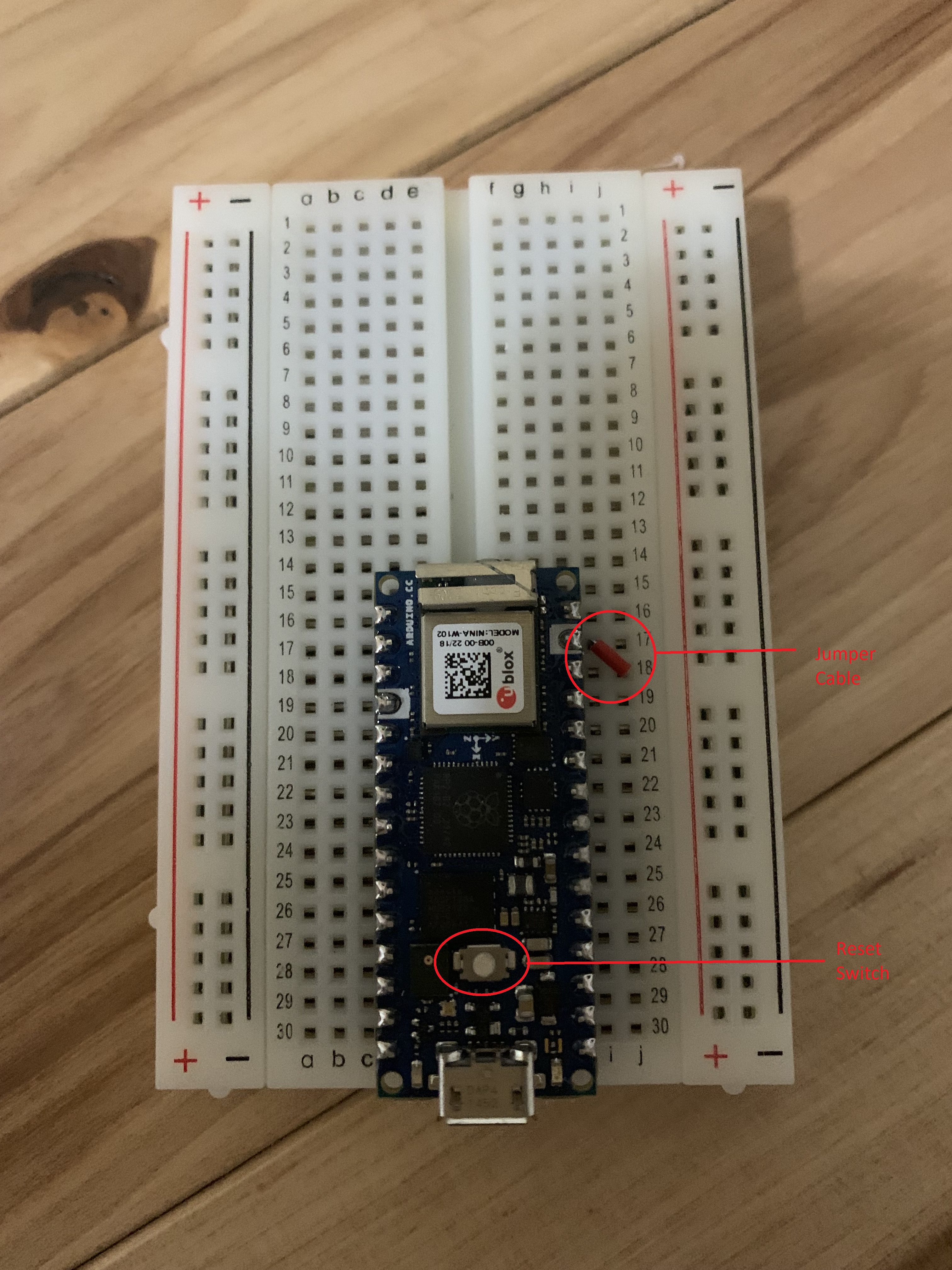
Insert it into breadboard as pictured
insert red jumper cable to connect the ground and reset pin. The ground pin is the one with the white marking. See picture
Plug RP2040 into USB. Press reset switch. The RP2040 should become a disk drive on your computer.
Go to your OS's shell and use Arduino-FWUploader to update the RP2040 to the latest NINA firmware.
arduino-fwuploader firmware flash -b arduino:mbed_nano:nanorp2040connect -a <port> -m NINA@<version>
When I ran it, I used:
arduino-fwuploader firmware flash -b arduino:mbed_nano:nanorp2040connect -a COM5 -m NINA@1.5.0
Open Thonny again.
In Thonny, type the following:
             import network, socket

             sta_if = network.WLAN(network.STA_IF)

             ap = network.WLAN(network.AP_IF) # create access-point interface

             ap.active(False)         # deactivate the interface

             if not sta_if.isconnected():

                print('connecting to network...')

                sta_if.active(True)

                sta_if.connect('Your WIFI SSID', 'your WIFI password')  # ADAPT

                while not sta_if.isconnected():

                  pass

             print('network config:', sta_if.ifconfig())  # Connection info

             a = sta_if.config('mac')

             print('MAC {:02x}:{:02x}:{:02x}:{:02x}:{:02x}:{:02x}'.format(a[0],a[1],a[2],a[3],a[4],a[5]))

             s=socket.socket(socket.AF_INET, socket.SOCK_STREAM)

             #host_ip = s.gethostbyname('cecilchua.online')

             s.connect(socket.getaddrinfo('cecilchua.online', 80)[0][-1])

             print("connected")

             s.write('GET /ist6336.htm HTTP/1.1\nHost: cecilchua.online\nsocket: close\n\n')

             print("written")

             reply= s.recv(4096)

             print(reply.decode('asc'))

             s.close()
If it produces the code for a simple web page, you did everything right.
Introduction to IoT and the Arduino MKR 1000/Nano RP 2040 Connect
These slides introduce students to the concept of IoT, the physical layout of an Arduino MKR 1000 and basic commands to make an LED blink on and off.
Making an LED Blink On and Off
Arduino MKR 1000
This lab is the standard introductory lab used for almost all Arduino boards. The official version can be found here. The version in this lab is specific to the MKR 1000 and shows screenshots of how the various components should be connected to the breadboard.
Arduino Nano RP 2040 Connect
This lab teaches students how to make the RP 2040 LED light blink. While variants of this lab exist for other Pico and RP 2040 boards, I can't find a version for the Nano RP 2040 Connect.
The Serial Port
These are lecture notes on the serial port and how to send messages through the serial port to debug code with. Note, the lecture is oriented around the MKR 1000, because while
the same issues occur with the Nano RP 2040 Connect, the issues are hidden by the print command which sends information through the serial port without the programmer needing to know how it is done.
Making the Arduino Read a Switch
Arduino MKR 1000
This is patterned after the standard second lab for Arduino
boards. Here, we teach the student how to connect a simple input device (a switch) to the Arduino.
The official version can be found
here.
Note there are certain key differences between the version in this tutorial versus the official one.
First, this lab assumes the Arduino MKR 1000 rather than the Arduino Uno. Second, students
are instructed to build their pushbutton circuit on top of the LED circuit. This is because in
future labs, they will use the pushbutton and LED together.
The lab teaches two important concepts. First, the lab introduces students to the idea of data streams- the pushbutton sends a data stream. Second, the lab introduces students to the idea of debugging using messages from the serial port.
Arduino Nano RP 2040 Connect
This is the equivalent lab for the Nano RP 2040 Connect. The programming style of this lab differs, because
interpreted Python is substantially slower than C++. Using the standard approach, the serial I/O bufer will fill too quickly and we can't see the switch work.
Processing Data Streams With Interrupts
This set of slides explains the idea of interrupts and how we use interrupts to manage the data stream coming from the pushbutton.
The LED and the Pushbutton
MKR 1000
This exercise teaches students how to turn the LED on and off with a pushbutton with the MKR 1000. The exercise employs an interrupt on the pushbutton such that every odd push turns the LED on, every even push turns it off.
Nano RP 2040 Connect
This exercise teaches students how to turn the LED on and off with a pushbutton with the Nano RP 2040 Connect in Python. The exercise employs an interrupt on the pushbutton such that every odd push turns the LED on, every even push turns it off.
Basic IoT Programming
These activities teach students how to send and receive messages over the Internet using the MKR 1000/Nano RP 2040 Connect.
Students learn how to directly communicate between Arduinos (which only works within an Intranet) and
how to make Representational State Transfer (REST) requests to a server using an Arduino.
Intranet Based Arduino Server
Note the following labs are compatible with each other. It is possible for a student using the MKR 1000 to connect to another student's Nano RP2040 Connect and vice-versa.
MKR 1000
This exercise demonstrates to students how an Arduino MKR 1000 can be configured as a server listening to messages on a port. Once the Arduino is programmed, students can test their code using TCP-based
communication software like PuTty or Netcat. In the end, students form pairs and have their individual devices communicate with each other.
Nano RP 2040 Connect
This exercise demonstrates to students how a Nano RP 2040 Connect can be configured as a server listening to messages on a port. Once the Arduino is programmed, students can test their code using TCP-based
communication software like PuTty or Netcat. In the end, students form pairs and have their individual devices communicate with each other.
Internet Based Arduino Communication
Communication over the Internet requires much more work. In this case, students communicate on a
server on the Internet. The video demonstrates the server with an older version of the
switch to LED device. I have since refined the lab to make the wiring neater.
The server uses Representational State Transfer (REST) to register the
Arduino MAC ID. The server employs the following REST commands:
Board registration- http://<server>/arduinoregister.php?boardid=<board MAC ID>. The board MAC ID is a 17 character string of the form 00-00-00-00-00-00. Board registration informs the server that the board exists.
Button pressed- http://<server>/arduinobutton.php?boardid=<board MAC ID>. This informs the server that a button was pressed. The server then reverses the state of the button in its memory, i.e., if the button state was off, it is set to on and vice-versa.
Map light to switch- http://<server>/arduinomaplighttoswitch.php?lightid=<board MAC ID>&switchid=<board MAC ID>. This allocates an LED to a particular button. It is possible to allocate multiple LEDs to one button and multiple buttons to one LED.
Present state of LED- http://<server>/arduinolight.php?boardid=<board MAC ID>. This presents the state of an LED- whether it should be on or off. The board should poll the server periodically to read this value to determine whether its LED should be lit.
Store temperature- http://<server>/arduinotemperature.php?boardid=<board MAC ID>&
tempinc=<celcius temperature>&tempinf=<farenheit temperature>. This stores the temperature reading of a device. Both the temperature in Celsius and Farenheit must be provided. While theoretically, these can be calculated from each other, the server does not do the calculation and stores both values separately.
Update power of motor- http://<server>/updatemotor.php?boardid=<board MAC ID>&
motorpower=<power>. This sets the motor of the Arduino. Legal values range from -255 to 255. A power level of 0 means the motor should be off.
Present power of motor- http://<server>/arduinomotorpower.php?boardid=<board MAC ID>. This tells the Arduino what power level to set the motor at from -255 to 255. A power level of 0 means the motor should be off.
The server also comes with a set of screens to display various things. An instance of the server can be found here:
These exercises teach students how to connect and use various electronic components with the Arduino.
It is necessary for students to be exposed to a range of electronic components to perform a meaningful
project.
The TMP-36 Temperature Sensor
MKR 1000
This exerise
teaches students how to read temperature readings from a TMP-36 temperature sensor and convert the readings to Celsius and Farenheit. Note while the Arduino 5V pin says it is a 5V pin, my experience
is it seems to only generate 3.3V. This is important in calibrating the TMP-36 temperature sensor.
MKR 1000
This exerise
teaches students how to read temperature readings from a TMP-36 temperature sensor and convert the readings to Celsius and Farenheit. A reasonable question to ask is why bother with the TMP-36
when the Nano RP 2040 Connect has its own internal temperature sensor. This is a useful exercise for a number of reasons. First, it teaches students how to perform analog to digital conversion
using the analog pins. Second, the internal temperature sensor is vulnerable to processing issues on the board. When the board gets hot, the temperature sensor reading rises regardless of the
ambient temperature.
The Light Sensor
This exercise: teaches students how to read light readings from a phototransistor.
The Piezoelectric Buzzer
MKR 1000
This exercise:teaches the student how to manipulate a simple speaker that allows your Arduino to play music.
Nano RP 2040 Connect
This exercise:teaches the student how to manipulate a simple speaker that allows your Arduino to play music.
The DC Motor and the L293D
MKR 1000
This exercise teaches you how to operate a motor using the Arduino. To operate the motor,
we will need to use a simple integrated circuit (IC) that allows us to convert variable strength
values into electronic pulses to make the motor run fast or slow.
Nano RP 2040 Connect
This exercise teaches you how to operate a motor using the Arduino. To operate the motor,
we will need to use a simple integrated circuit (IC) that allows us to convert variable strength
values into electronic pulses to make the motor run fast or slow.
The LCD Display
This is the official lab for running the LCD display from Arduino.
The lab employs an Arduino Uno as the board, but it works fine with the MKR 1000.
The Gyroscope and the Accelerometer
This lab teaches students how to use the Arduino's gyro and accelerometer. Students learn how to program the Arduino so tilting the
Arduino left and right, up and down causes a horse on screen to move left, right, up and down respectively. The horse in this exercise is found at
cecilchua.online/arduino/gyrohorse.htm. This horse is controlled by a PHP file gyroread.php.
Sending:
The exercise involves teaching students how to read the gyroscope sensor to interpret the equivalent of left, right, up and down to then send to gyroread.php.